
Extrication Tips: July 2013
Randy Schmitz
Features Extrication TrainingOver the last few years, the Province of Alberta’s efforts to improve highway safety have included roadway engineering to help drivers keep their cars on the road and to reduce the safety consequences when they fail to do so.
Over the last few years, the Province of Alberta’s efforts to improve highway safety have included roadway engineering to help drivers keep their cars on the road and to reduce the safety consequences when they fail to do so.
The province has installed rumble strips, improved and straightened curves, widened highway shoulders, upgraded medians and installed median barriers.
Median barriers are generally installed along divided highways to provide a physical barrier between opposing traffic streams with the intention of eliminating cross-median collisions – which have the potential to be severe – by intercepting an errant vehicle before it crosses into opposing traffic.
While no barrier can eliminate the consequences for every driver who runs off the road, cable median barriers have been proven to reduce the number of vehicles that enter into oncoming traffic after crossing a median.
The barrier is designed to minimize the forces on the occupants in a vehicle that hits the barrier, and to provide some capacity to redirect the vehicle in a controlled manner, or bring the vehicle to a controlled stop.
Emergency responders need to be made aware of these barrier systems and train for rescue efforts where a vehicle is entwined in a cable barrier. For example, safe cutting procedures need to be defined when they become necessary. Emergency-response agencies should have educational materials that provide responders with clear and concise guidance on when and how to safely disconnect or cut cables when a vehicle is entangled after an impact.
We will focus on high-tension cable barrier systems (HTCBs), their design and function.
Although there are five manufacturers of HTCBs – Gibraltar, Nucore, Safence, Marion and Trinity – Gibraltar is the most commonly installed system in Canada.
Overview of HTCB systems
HTCB systems have three or four galvanized steel cables, each measuring 19 millimetres (3/4 inch) in diameter. Each of those cables comprises three seven-piece strands of steel, and is held at the desired height by weak steel posts placed in sleeves in concrete or steel foundations. The cables are individually connected to end terminals, which are also anchored in steel or concrete foundations.
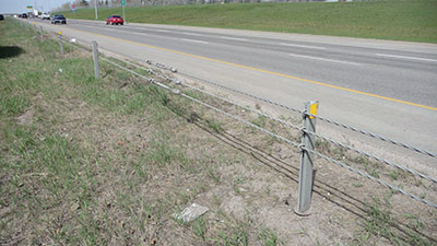
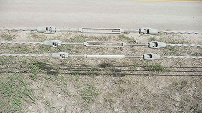
Cables are, in most cases, pre-stretched and post-tensioned after installation to a value depending on ambient temperature – for example, 2,540 kilograms (5,600 pounds) at 21 C. The posts are expected to break away on impact, and the tensioned cables deflect and cushion the force of the hitting vehicle. Cables are typically supplied in 303-metre (994-foot) lengths and are connected by turnbuckles or acorns (see photo 1). The cables are very strong and will normally deflect, but not break, in typical highway crashes.
There are many factors that influence the reaction of a vehicle when traversing sloped terrain. Primary factors include vehicle mass, vehicle speed, angle of departure and the slope of the terrain. Secondary factors include the distribution of vehicle load, the condition of vehicle subsystems (for example, the vehicle’s suspension), the surface conditions, driver control inputs and surface friction.
Benefits of the cable barrier
- The system can sustain hits and still remain effective.
- On average, four to five posts require repair after a crash and repairs take 10 to 30 minutes to complete.
- The number of incidents may increase, but the severity of those incidents is dramatically reduced.
- The system is relatively inexpensive compared to other types of barriers.
Cable barriers also perform better than other barriers when installed on moderately sloping terrain, which is common around many medians.
Types of cable barriers
Low- or non-tensioned post and cable barriers, which are also referred to as generic cable barriers, have been used for vehicle containment on highways since the 1940s. The major drawback is that, after a collision, the cables lose their ability to withstand additional hits until the damaged posts are replaced and the cables are re-attached at the proper heights.
HTCB systems, which are tightened to a specified temperature-dependent tension, retain their tension and cable height even after a hit – and can take additional hits until the posts are replaced. High-tension cable barriers have proven their effectiveness in drastically reducing cross-over collisions on divided (and undivided) highways in Europe and elsewhere. In the United States, several thousand kilometres of high-tension cable barriers have been installed as freeway medians over the last few years.
Appealing HTCB features
- Aesthetic appeal
- Reduced snow drift
- Reduced collision severity
- Low occupant risk/longer deflections
- Reduced installation cost
- Ease of repair
- Ease of inspection
- Ability to provide protection even after impact and prior to repairs
Cost effectiveness
In Calgary in 2007, the cost of the Gibraltar high-tension cable barrier was $92 per metre, which compared to the Alberta provincial average of $125 per metre for a W-beam steel guardrail and $308 per metre for a concrete barrier. The maintenance and repair costs are $4.14 per metre for the high-tension cable, compared to $6.74 per metre for W-beam guardrails and $1.72 per metre for concrete barriers.
Safety for repair crews
Repair and maintenance times for cable barriers are far shorter than those for other barrier systems: most repairs take less than three hours and are done on the same day that the barrier is hit. Since cable-barrier repairs take less time to complete, repair crews are not left working in dangerous highway conditions for as long they would be if they were to repair other barrier types. The cable barrier is also visually pleasing and does not impede a driver’s view, unlike beam guardrails or concrete barriers. When hit by a vehicle, the tension maintains the cable’s designed height, even when the posts have been damaged or have broken off.
Mandatory safety provisions
All HTCB systems are subjected to a testing program called Procedures for the Safety Performance Evaluation of Highway Features, which is published by the National Cooperative Highway Research Program. To date, there are six test levels. TL-1, TL-2 and TL-3 tests are the most common, and involve two test vehicles: an 820-kilogram (1,807-pound) car, and a 2,000-kilogram (4,409-pound) pickup truck.
The TL-4 test adds a third vehicle, an 8,000-kilogram (17,637-pound) single-unit truck, while the TL-5 test substitutes a 36,000-kilogram (79,366-pound) tractor/van for the single-unit truck in the TL-4 test. The TL-6 substitutes a 36,000-kilogram (79,366-pound) tractor/tank trailer for the single-unit truck in the TL-4 test.
Currently, no cable barriers are made to the TL-5 and TL-6 levels.
Design, function and operation
 |
|
| Photo 1: Cables are typically supplied in 303-metre lengths and are connected by turnbuckles or acorns. Photos By Randy Schmitz |
|
 |
|
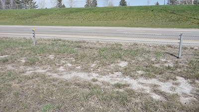
| Photo 2: Post spacing has a direct effect on the deflection space created when hit; the farther apart the posts are from each other, the more deflection there will be.
|
Run length of HTCB
The distance between anchor terminals is generally referred to as a cable run or run length. Technically speaking, there are no boundaries to the length of a single, uninterrupted run of cable. However, longer cable runs require more effort to tension and re-tension, and there are more maintenance/replacement problems with long lengths. The presence of overpass structures, at-grade intersections and emergency/maintenance crossovers also dictate run length.
Vehicle deflection distance
The deflection distance of a vehicle, which measures the space into which the vehicle bounces back after it hits a cable barrier, is an important feature and is impacted by many characteristics, including cable tension and post spacing. Compared to other types of barriers, such as concrete or semi-rigid W-beam barriers, cable barriers have much greater deflection distances, which is why cable barriers usually are more tolerant to the impacting vehicle’s passengers.
Regardless, in order for the cable barrier to be safe, there must be sufficient space beside the barrier that is clear of hazards. If deflections are too large, the impacting vehicle could crash into rigid objects behind the barrier or, worse yet, collide with a vehicle in the opposing lane of traffic on a divided highway.
Post spacing
Post spacing has a direct effect on the deflection space created when hit. A general rule is that the farther apart the posts are from each other, the more deflection there will be (see photos 1 and 2).
2.8 metres (9.2 feet) = 9.1 metres (29.9 feet)
2.7 metres (8.9 feet) = 8.5 metres (27.9 feet)
2.4 metres (7.9 feet) = 6.0 metres (19.7 feet)
2.1 metres (6.9 feet) = 3.6 metres (11.8 feet)
Cable tension
The tension in the cables works to redirect the vehicle after a collision. However, cable tension changes with temperature – increasing in cold weather and decreasing in warm weather due to thermal contraction/expansion. Slight changes in tension do not have a substantial effect on deflection. Lower tensions allow some increase in deflection, but higher tensions apply higher static loads on the end anchors and cable release posts, principally during cold weather.
Because of the day-to-day differences in tension due to climactic changes, cable barrier tension can fluctuate by about 992 kilograms (450 pounds). A digital gauge is used to check the tension of the wire.
HTCB system placement
HTCB systems are generally offset from the very bottom or centre of the median, which often acts as a drainage ditch between two opposing roadways. Thus, saturated soil conditions are quite common, making it difficult to keep line posts upright and intact. The soil will be more stable and predictable if the HTCB system is placed farther up the slope in drier conditions and near level terrain. Another reason is that, as a vehicle enters the cables, its front suspension will be completely compressed as the front end of the vehicle reaches the deepest part of the ditch. This puts the front end of the vehicle at risk of riding under the bottom cable and getting through the barrier.
Physical makeup of the system
 |
|
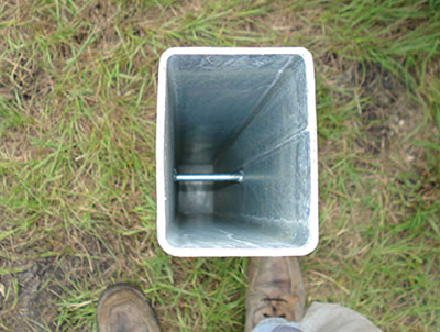
| Photo 3: This photo shows the top of a galvanized steel C-post. These posts are set into a 38-centimetre sleeve of steel, called a socket, which is embedded in a concrete footing that measures 30 centimetres wide and 1.2 metres deep. |
|
 |
|
| Photo 4: A 60-centimetre by 19-millimetre threaded rod, attached by acorns to the cable, allows for tensioning and readjustment. |
Post construction
Photo 3 shows the top of a galvanized steel C-post, also known as a line post, which measures nine centimetres by six centimetres by 1.6 metres (3.5 inches by 2.4 inches by 5.2 feet). These posts are set into a 38-centimetre (15-inch) sleeve of steel, called a socket. The socket is embedded in a concrete footing that measures 30 centimetres (11.8 inches) wide and 1.2 metres (3.9 feet) deep. If installed without a concrete footing, the post must be driven directly into the ground to a deeper depth, between 1.5 metres and 2.1 metres (4.9 feet and 6.9 feet).
Hair pin
A galvanized round bar, measuring 11 millimetres (0.4 inches) thick, is designed to hold the cable in position and correct the cable’s height to the post. The bar, called a hair pin, can hold all three or four cables at once.
Lock plate
A galvanized steel flat bar, which measures 30 centimetres (11.8 inches) long, three millimetres (0.1 inches) thick and 25 millimetres (one inch) wide, keeps the hair pin in place. Notched slots in the lock plate fit around the hair pins, which adheres it to the post.
Turnbuckle
A 60-centimetre (23.6-inch) by 19-millimetre (0.75-inch) threaded rod, attached by acorns to the cable, allows for tensioning and readjustment (see photo 4).
Cable or steel wire rope
Invented in the 1830s, the cables have a nominal 19-millimetre (0.75-inch) diameter. Each cable consists of three bundles of seven wires each, with a right-hand-lay helical twist. The cables have an 18,000-kilogram (39,683-pound) breaking strength. They also alternate on either side of the post to allow for hits from both directions.
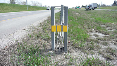
Cable release post
 |
|
| Photo 5: This anchor post is designed to pry the cable ends out of slots in the base plate when it is run into, thus letting go of all cable tension and allowing a vehicle to pass over the terminal with a somewhat stable trajectory.
|
The cable release post comprises two galvanized steel posts (see photo 5), each measuring five centimetres (two inches) by 10 centimetres (four inches) by nine millimetres (0.4 inches). The posts are welded to a 19-millimetre-thick (0.75-inch-thick) steel base plate.
This anchor post rests on a 13-millimetre (0.5-inch) base plate that is welded to a galvanized 76-centimetre-long (29.9-inch-long) tube, which measures 20 centimetres (7.9 inches) by 20 centimetres (7.9 inches) by nine millimetres (0.03 inches). The baseplate is set in a reinforced concrete foundation that is 1.8 metres (5.9 feet) deep and 60 centimetres (23.6 inches) in diameter.
This anchor post is designed to pry the cable ends out of slots in the base plate when it is run into, thus letting go of all cable tension and allowing a vehicle to pass over the terminal with a somewhat stable trajectory.
End anchors
Typically, the point at which the HTCB systems begin and terminate are called end anchors. Anchoring the HTCB is extremely important to ensure that it performs adequately during and after a hit. If the anchoring system is not properly secured in the ground, movement of the system could result in lower tension in the cables, which results in larger deflection of the system. The movement could also lead to the cables sagging, which affects cable height and can also affect the barrier’s ability to capture a vehicle. Anchor movements are often attributed to weak soil conditions and the substandard-sized anchors. As a result, different sized concrete footings are required for different soil environments.
Weather conditions also lead to anchor movement. Decreases in temperature lead to higher cable tensions, which, in turn, apply higher forces on the anchors.
Cons of the system
Repairs after crashes
Cable barriers are used predominantly along narrow medians of high-traffic highways, and they tend to get hit fairly often; this can increase the maintenance cost if the installation is close to the roadway as opposed to the ditch or offset in the median. Also, frequent hits can make it more difficult for the maintenance crews to keep up with repairs, especially during poor weather and icy conditions.
All current cable barriers have weak posts that are damaged in a crash and must be replaced. These posts are typically driven in soil, placed in sockets embedded in concrete foundations, or placed in driven sockets. Damaged driven posts may require special equipment for replacement. Socketed posts, on the other hand, can usually be replaced without specialized equipment, reducing the repair cost. Most repair jobs are done with a standard high lift jack to pull the post out of the socket. Post extraction problems can occur during subfreezing weather because the posts are often frozen in their sockets. In cold-weather areas such as southern Alberta, expandable foam is sprayed in and around the socket to keep freezing water out and to allow for easier post extraction. Lengthy extraction problems also can occur when posts are sheared off at ground level rather than bent over.
Case study
Let’s look at the engineered safety features and collision-reduction results for a TL-4 high-tension post and cable barrier. The barrier was completed in May 2007 in the median of an 11-kilometre (6.8-mile) stretch of the Deerfoot Trail, an urban freeway in Calgary.
Between 1999 and 2005, there were seven fatal crossover collisions on that segment of the Deerfoot Trail. The six-lane divided urban freeway between 16th Avenue and Country Hills Boulevard carries up to 150,000 vehicles a day. As a result of those fatalities, a case study was conducted for Alberta Infrastructure and Transportation, and focused along a section of the Deerfoot Trail.
The purpose of the study was to assess the existing median conditions and determine what improvements may be considered to reduce the overall risk of collisions.
The system has been in use for several years in Europe, Australia and New Zealand, and has established a reputation for effective, easy, low-cost maintenance and repair. Tensioned barrier systems are bidirectional, meaning that they can take hits from either side and contain a vehicle.
Since the high-tension median cable barrier has been installed, however, there have been no crossover collisions on that section of roadway at all. This relatively new type of median barrier has proven so successful at preventing crossover collisions that Alberta Transportation has also installed it on 144 kilometres (89.5 miles) on Highway 2 between Calgary and Leduc.
While high-tension median cables are life saving, they are not approved for medians with steep side slopes. They are also not suitable for narrow medians that lack the space for the cable barrier to deflect.
Some motorcyclists have expressed concerns over cable barriers. Researchers in other parts of the world, such as the United Kingdom, however, have found little difference between crashes into cable median barriers and those into other barrier types. According to the data, most riders are separated from their motorcycles soon after leaving the pavement and are sliding on the ground by the time they reach the barrier. The data also did not show that cable barriers cause extraordinary injuries.
During the 34-month operation (May 2007 to February 2010) of the median cable barrier on the Deerfoot Trail, there were 135 incidents of vehicles hitting the cable barrier resulting in the replacement of posts, hair pins and/or lock plates. No crossover fatal collisions occurred in these 34 months (almost three years), compared to seven fatal crossover collisions in the seven-year period, from 1999 to 2005, on the same section of the Deerfoot Trail.
Alberta Transportation has become a major pioneer in Canada for this road safety measure. The 11-kilometre (6.8-mile) installation on the Deerfoot Trail was the first major high-tension median cable guardrail project in Canada. Since it has been proven to be an effective means of protecting Canadian motorists, more of these types of barriers are being installed across Canada. As first responders, we need to be prepared to deal with these systems; in the next issue we will look at ways to deal with cable barrier problems.
Randy Schmitz is a Calgary firefighter who has been extensively involved in the extrication field for 19 years. He is an extrication instructor and has competed internationally. He is the education chair for Transport Emergency Rescue Committee (T.E.R.C.) in Canada, a T.E.R.C. International extrication judge and a tester and evaluator for manufactured prototype products for extrication equipment. He can be reached at rwschmitz@shaw.ca. Follow him on Twitter at @firedog7
Print this page